Cisco® 300-135 Exam Practice Questions (P. 4)
- Full Access (154 questions)
- One Year of Premium Access
- Access to one million comments
- Seamless ChatGPT Integration
- Ability to download PDF files
- Anki Flashcard files for revision
- No Captcha & No AdSense
- Advanced Exam Configuration
Question #16
Instructions -
The main screen consists of two parts; the Main scenario and the Topology tabs. The main scenario describes TSHOOT.com test bed. The Topology tabs allow you to display the appropriate and select the trouble ticket.
To complete the item, you will first need to familiarize yourself with the TSHOOT.com test bed by clicking on the master scenario first and then the topologies tabs.
Once you are familiar with the test bed and the topologies, you should start evaluating the trouble ticket. You will be presented with a Trouble Ticket scenario that will describe the fault condition. You will need to determine on which device the fault condition is located, to which technology the fault condition is related, and the solution to each trouble ticket. This will be done by answering three questions.
Ticket Selection -
✑ To begin, click on the Ticket on the Topology tabs.
Some of the questions will require you to use the scroll bar to see all options.
✑ Please note.
Fault Isolation -
✑ Read the ticket scenario to understand the fault condition.
✑ Open the appropriate topology, based upon the ticket scenario.
✑ Open the console of the desired device by clicking on that device in the topology, based upon your troubleshooting methodology.
✑ Use the supported show, ping and trace commands to begin your fault isolation process.
✑ Move to other devices as need by clicking on those devices within the topology.
Fault Identification -
✑ The trouble ticket will include three questions that you will need to answer:
1. Which device contains the fault
2. Which technology the fault condition is related to
3. What is the solution to the issue
✑ To advance to the next question within the ticket click on "Next Question".
✑ When you click "DONE", the trouble ticket will turn RED and will no longer be accessible.
✑ You may also use the "Previous Question" button to review questions within that specific ticket.
✑ To complete a trouble ticket, answer all three questions and click "DONE". This will store your response to the questions. Do not click on "DONE" unless you have answered all questions within the ticket.
Item Completion -
✑ Click the NEXT button on the bottom of the screen once a ticket is RED. This action moves you to the next item.
Scenario -
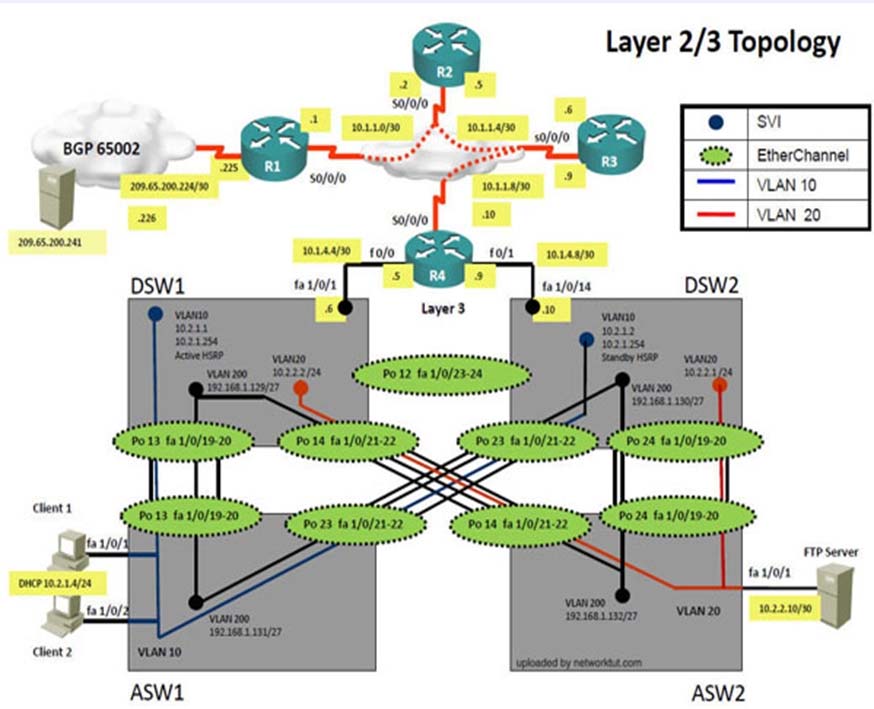
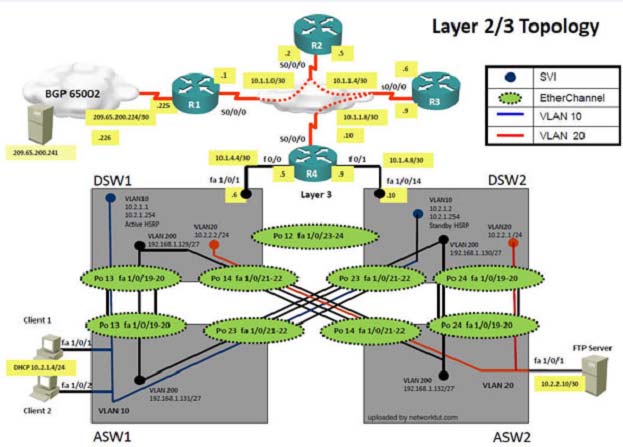
The company has created the test bed network shown in the layer 2 and layer 3 topology exhibits.
This network consists of four routers, two layer 3 switches and two layer 2 switches.
In the IPv4 layer 3 topology, R1, R2, R3, and R4 are running OSPF with an OSPF process number 1.
DSW1, DSW2 and R4 are running EIGRP with an AS of 10. Redistribution is enabled where necessary.
R1 is running a BGP AS with a number of 65001. This AS has an eBGP connection to AS 65002 in the ISP's network. Because the company's address space is in the private range, R1 is also providing NAT translations between the inside (10.1.0.0/16 & 10.2.0.0/16) networks and the outside (209.65.200.0/24) network.
ASW1 and ASW2 are layer 2 switches.
NTP is enabled on all devices with 209.65.200.226 serving as the master clock source.
The client workstations receive their IP address and default gateway via R4's DHCP server. The default gateway address of 10.2.1.254 is the IP address of HSRP group 10 which is running on DSW1 and DSW2.
In the IPv6 layer 3 topology R1, R2, and R3 are running OSPFv3 with an OSPF process number 6. DSW1, DSW2 and R4 are running RIPng process name
RIP_ZONE. The two IPv6 routing domains, OSPF 6 and RIPng are connected via GRE tunnel running over the underlying IPv4 OSPF domain. Redistribution is enabled where necessary.
Recently the implementation group has been using the test bed to do a "˜proof-of-concept' on several implementations. This involved changing the configuration on one or more of the devices. You will be presented with a series of trouble tickets related to issues introduced during these configurations.
The implementation group has been using the test bed to do a "˜proof-of-concept' that requires both Client 1 and Client 2 to access the WEB Server at
209.65.200.241. After several changes to the network addressing, routing schemes, DHCP services, NTP services, and FHRP services, a trouble ticket has been opened indicating that Client 1 cannot ping the 209.65.200.241 address.
Use the supported commands to isolate the cause of this fault and answer the following questions.
The fault condition is related to which technology?
The main screen consists of two parts; the Main scenario and the Topology tabs. The main scenario describes TSHOOT.com test bed. The Topology tabs allow you to display the appropriate and select the trouble ticket.
To complete the item, you will first need to familiarize yourself with the TSHOOT.com test bed by clicking on the master scenario first and then the topologies tabs.
Once you are familiar with the test bed and the topologies, you should start evaluating the trouble ticket. You will be presented with a Trouble Ticket scenario that will describe the fault condition. You will need to determine on which device the fault condition is located, to which technology the fault condition is related, and the solution to each trouble ticket. This will be done by answering three questions.
Ticket Selection -
✑ To begin, click on the Ticket on the Topology tabs.
Some of the questions will require you to use the scroll bar to see all options.
✑ Please note.
Fault Isolation -
✑ Read the ticket scenario to understand the fault condition.
✑ Open the appropriate topology, based upon the ticket scenario.
✑ Open the console of the desired device by clicking on that device in the topology, based upon your troubleshooting methodology.
✑ Use the supported show, ping and trace commands to begin your fault isolation process.
✑ Move to other devices as need by clicking on those devices within the topology.
Fault Identification -
✑ The trouble ticket will include three questions that you will need to answer:
1. Which device contains the fault
2. Which technology the fault condition is related to
3. What is the solution to the issue
✑ To advance to the next question within the ticket click on "Next Question".
✑ When you click "DONE", the trouble ticket will turn RED and will no longer be accessible.
✑ You may also use the "Previous Question" button to review questions within that specific ticket.
✑ To complete a trouble ticket, answer all three questions and click "DONE". This will store your response to the questions. Do not click on "DONE" unless you have answered all questions within the ticket.
Item Completion -
✑ Click the NEXT button on the bottom of the screen once a ticket is RED. This action moves you to the next item.
Scenario -
The company has created the test bed network shown in the layer 2 and layer 3 topology exhibits.
This network consists of four routers, two layer 3 switches and two layer 2 switches.
In the IPv4 layer 3 topology, R1, R2, R3, and R4 are running OSPF with an OSPF process number 1.
DSW1, DSW2 and R4 are running EIGRP with an AS of 10. Redistribution is enabled where necessary.
R1 is running a BGP AS with a number of 65001. This AS has an eBGP connection to AS 65002 in the ISP's network. Because the company's address space is in the private range, R1 is also providing NAT translations between the inside (10.1.0.0/16 & 10.2.0.0/16) networks and the outside (209.65.200.0/24) network.
ASW1 and ASW2 are layer 2 switches.
NTP is enabled on all devices with 209.65.200.226 serving as the master clock source.
The client workstations receive their IP address and default gateway via R4's DHCP server. The default gateway address of 10.2.1.254 is the IP address of HSRP group 10 which is running on DSW1 and DSW2.
In the IPv6 layer 3 topology R1, R2, and R3 are running OSPFv3 with an OSPF process number 6. DSW1, DSW2 and R4 are running RIPng process name
RIP_ZONE. The two IPv6 routing domains, OSPF 6 and RIPng are connected via GRE tunnel running over the underlying IPv4 OSPF domain. Redistribution is enabled where necessary.
Recently the implementation group has been using the test bed to do a "˜proof-of-concept' on several implementations. This involved changing the configuration on one or more of the devices. You will be presented with a series of trouble tickets related to issues introduced during these configurations.
The implementation group has been using the test bed to do a "˜proof-of-concept' that requires both Client 1 and Client 2 to access the WEB Server at
209.65.200.241. After several changes to the network addressing, routing schemes, DHCP services, NTP services, and FHRP services, a trouble ticket has been opened indicating that Client 1 cannot ping the 209.65.200.241 address.
Use the supported commands to isolate the cause of this fault and answer the following questions.
The fault condition is related to which technology?
Question #17
Instructions -
The main screen consists of two parts; the Main scenario and the Topology tabs. The main scenario describes TSHOOT.com test bed. The Topology tabs allow you to display the appropriate and select the trouble ticket.
To complete the item, you will first need to familiarize yourself with the TSHOOT.com test bed by clicking on the master scenario first and then the topologies tabs.
Once you are familiar with the test bed and the topologies, you should start evaluating the trouble ticket. You will be presented with a Trouble Ticket scenario that will describe the fault condition. You will need to determine on which device the fault condition is located, to which technology the fault condition is related, and the solution to each trouble ticket. This will be done by answering three questions.
Ticket Selection -
✑ To begin, click on the Ticket on the Topology tabs.
Some of the questions will require you to use the scroll bar to see all options.
✑ Please note.
Fault Isolation -
✑ Read the ticket scenario to understand the fault condition.
✑ Open the appropriate topology, based upon the ticket scenario.
✑ Open the console of the desired device by clicking on that device in the topology, based upon your troubleshooting methodology.
✑ Use the supported show, ping and trace commands to begin your fault isolation process.
✑ Move to other devices as need by clicking on those devices within the topology.
Fault Identification -
✑ The trouble ticket will include three questions that you will need to answer:
1. Which device contains the fault
2. Which technology the fault condition is related to
3. What is the solution to the issue
✑ To advance to the next question within the ticket click on "Next Question".
✑ When you click "DONE", the trouble ticket will turn RED and will no longer be accessible.
✑ You may also use the "Previous Question" button to review questions within that specific ticket.
✑ To complete a trouble ticket, answer all three questions and click "DONE". This will store your response to the questions. Do not click on "DONE" unless you have answered all questions within the ticket.
Item Completion -
✑ Click the NEXT button on the bottom of the screen once a ticket is RED. This action moves you to the next item.
Scenario -
The company has created the test bed network shown in the layer 2 and layer 3 topology exhibits.
This network consists of four routers, two layer 3 switches and two layer 2 switches.
In the IPv4 layer 3 topology, R1, R2, R3, and R4 are running OSPF with an OSPF process number 1.
DSW1, DSW2 and R4 are running EIGRP with an AS of 10. Redistribution is enabled where necessary.
R1 is running a BGP AS with a number of 65001. This AS has an eBGP connection to AS 65002 in the ISP's network. Because the company's address space is in the private range, R1 is also providing NAT translations between the inside (10.1.0.0/16 & 10.2.0.0/16) networks and the outside (209.65.200.0/24) network.
ASW1 and ASW2 are layer 2 switches.
NTP is enabled on all devices with 209.65.200.226 serving as the master clock source.
The client workstations receive their IP address and default gateway via R4's DHCP server. The default gateway address of 10.2.1.254 is the IP address of HSRP group 10 which is running on DSW1 and DSW2.
In the IPv6 layer 3 topology R1, R2, and R3 are running OSPFv3 with an OSPF process number 6. DSW1, DSW2 and R4 are running RIPng process name
RIP_ZONE. The two IPv6 routing domains, OSPF 6 and RIPng are connected via GRE tunnel running over the underlying IPv4 OSPF domain. Redistribution is enabled where necessary.
Recently the implementation group has been using the test bed to do a "˜proof-of-concept' on several implementations. This involved changing the configuration on one or more of the devices. You will be presented with a series of trouble tickets related to issues introduced during these configurations.
The implementation group has been using the test bed to do a "˜proof-of-concept' that requires both Client 1 and Client 2 to access the WEB Server at
209.65.200.241. After several changes to the network addressing, routing scheme, DHCP services, NTP services, and FHRP services, a trouble ticket has been opened indicating that Client 1 cannot ping the 209.65.200.241 address.
Use the supported commands to isolate the cause of this fault and answer the following questions.
What is the solution to the fault condition?
Question #18
SIMULATION -
Scenario -
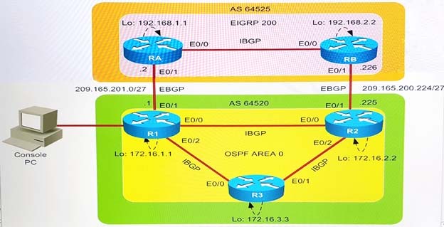
You work as Network Engineer for RADO Network Ltd company. Your colleague has set up a РОС lab that simulates a customer network to study about the behavior of BGP protocol when routes are exchanged between two different autonomous systems.
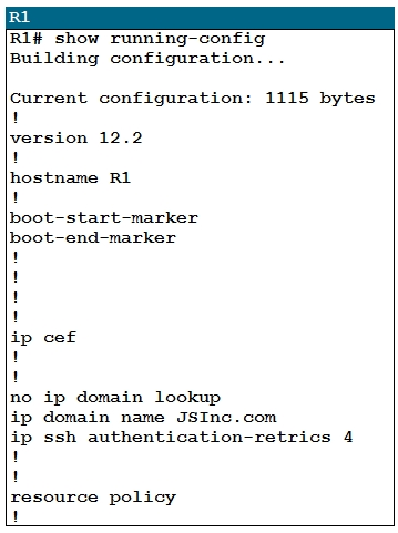
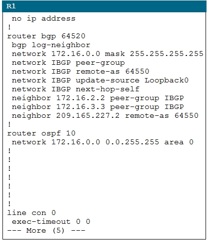
Review the topology. You must identify and fix IBGP and EBGP issues on R1 router.
Topology Details -
AS64520 -
✑ R1, R2, and R3 are three routers on AS 64520, and OSPF is the IGP routing protocol that is configured between them.
✑ IBGP is configured between R1, R2, and R3 routers using peer group.
✑ Loopback0 address is used for IBGP peering. Loopback0 address configured on R1, R2, and R3 are advertised into BGP domain on AS64525.
AS64525 -
✑ RA and RB are two routers on AS 64525, and EIGRP is the IGP routing protocol that is configured between them.
✑ Loopback0 address is used for IBGP peering. Loopback0 address is configured on RA and RB and it is advertised into the BGP domain on AS64525.
✑ R1 and RA form a EBGP neighbor relationship using a physical interface address.
✑ R2 and RB form a EBGP neighbor relationship using a physical interface address.
Simulation Requirements -
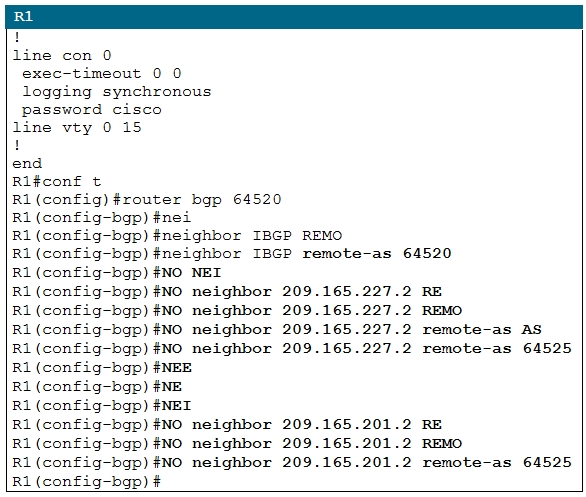
✑ Identify and fix the EBGP neighbor relationship issue between R1 and RA routers.
✑ Identify and fix the IBGP neighbor relationship issue between R1 and R2, and R1, and R3.
✑ You are allowed to remove any misconfiguration or incorrect configuration to only fix the issue. Other initial configurations that do not impact the issues must not be changed.
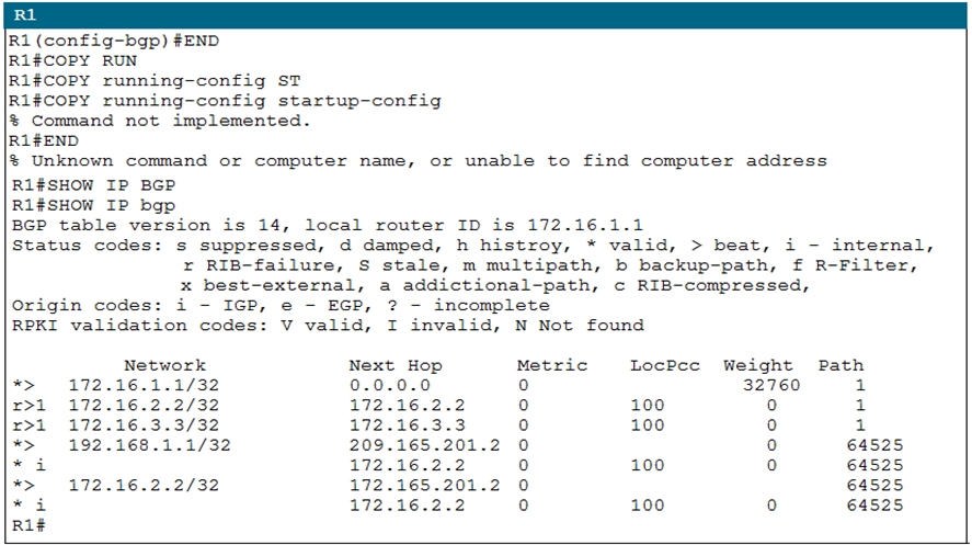
✑ After you fix two issues on the R1 router, the final BGP table must appear as shown here.
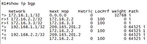
To gain the maximum number of points, you must fix IBGP and EBGP neighbor issues on router R1.
Special Note:
✑ BGP must be configured without using address families. Do not change the BGP peer group name.
✑ Console logging and debugging features are disabled.
✑ Use show commands to verify the BGP neighbor relationship.
Instructions -
To configure a router, click the console host icon in the topology.
To view the different windows, click the buttons at the bottom of the window.
To minimize the windows, click the [-]. To move a window, drag it by the title bar.
Most commands that use the "Control" or "Escape" keys are not supported and are not necessary to complete this simulation. The help command does not display all commands of the help system.
Console access is available to router R1.
The password that is configured on router R1 is cisco (all small letters).
(Console cable is connected between PC and R1.)
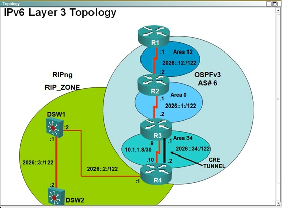
Topology -
Scenario -
You work as Network Engineer for RADO Network Ltd company. Your colleague has set up a РОС lab that simulates a customer network to study about the behavior of BGP protocol when routes are exchanged between two different autonomous systems.
Review the topology. You must identify and fix IBGP and EBGP issues on R1 router.
Topology Details -
AS64520 -
✑ R1, R2, and R3 are three routers on AS 64520, and OSPF is the IGP routing protocol that is configured between them.
✑ IBGP is configured between R1, R2, and R3 routers using peer group.
✑ Loopback0 address is used for IBGP peering. Loopback0 address configured on R1, R2, and R3 are advertised into BGP domain on AS64525.
AS64525 -
✑ RA and RB are two routers on AS 64525, and EIGRP is the IGP routing protocol that is configured between them.
✑ Loopback0 address is used for IBGP peering. Loopback0 address is configured on RA and RB and it is advertised into the BGP domain on AS64525.
✑ R1 and RA form a EBGP neighbor relationship using a physical interface address.
✑ R2 and RB form a EBGP neighbor relationship using a physical interface address.
Simulation Requirements -
✑ Identify and fix the EBGP neighbor relationship issue between R1 and RA routers.
✑ Identify and fix the IBGP neighbor relationship issue between R1 and R2, and R1, and R3.
✑ You are allowed to remove any misconfiguration or incorrect configuration to only fix the issue. Other initial configurations that do not impact the issues must not be changed.
✑ After you fix two issues on the R1 router, the final BGP table must appear as shown here.
To gain the maximum number of points, you must fix IBGP and EBGP neighbor issues on router R1.
Special Note:
✑ BGP must be configured without using address families. Do not change the BGP peer group name.
✑ Console logging and debugging features are disabled.
✑ Use show commands to verify the BGP neighbor relationship.
Instructions -
To configure a router, click the console host icon in the topology.
To view the different windows, click the buttons at the bottom of the window.
To minimize the windows, click the [-]. To move a window, drag it by the title bar.
Most commands that use the "Control" or "Escape" keys are not supported and are not necessary to complete this simulation. The help command does not display all commands of the help system.
Console access is available to router R1.
The password that is configured on router R1 is cisco (all small letters).
(Console cable is connected between PC and R1.)
Topology -
Question #19
Exhibit:
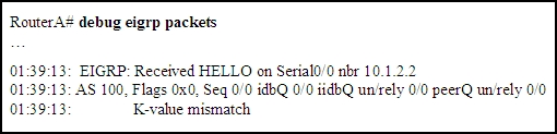
A network administrator is troubleshooting an EIGRP connection between RouterA, IP address 10.1.2.1, and RouterB, IP address 10.1.2.2. Given the debug output on RouterA, which two statements are true? (Choose two.)
A network administrator is troubleshooting an EIGRP connection between RouterA, IP address 10.1.2.1, and RouterB, IP address 10.1.2.2. Given the debug output on RouterA, which two statements are true? (Choose two.)
All Pages