Cisco® 300-135 Exam Practice Questions (P. 3)
- Full Access (154 questions)
- One Year of Premium Access
- Access to one million comments
- Seamless ChatGPT Integration
- Ability to download PDF files
- Anki Flashcard files for revision
- No Captcha & No AdSense
- Advanced Exam Configuration
Question #11
Scenario:
A customer network engineer has edited their OSPF network configuration and now your customer is experiencing network issues. They have contacted you to resolve the issues and return the network to full functionality.
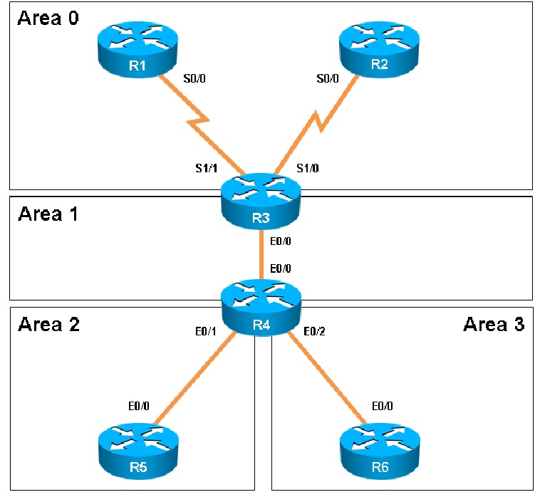


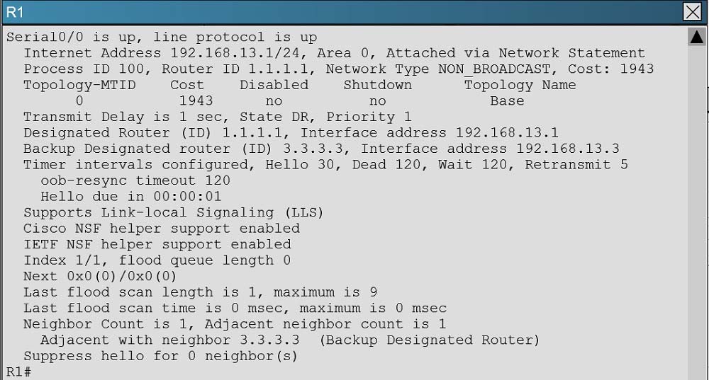
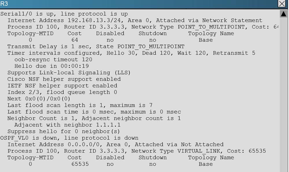
The OSPF neighbor relationship has been lost between R1 and R3. What is causing this problem?
A customer network engineer has edited their OSPF network configuration and now your customer is experiencing network issues. They have contacted you to resolve the issues and return the network to full functionality.
The OSPF neighbor relationship has been lost between R1 and R3. What is causing this problem?
- AThe serial interface in R1 should be taken out of the shutdown state.
- BA neighbor statement needs to be configured in R1 and R3 pointing at each other.
- CThe R1 network type should be changed to point-to-multipoint non-broadcast.
- DThe hello, dead and wait timers on R1 need to be reconfigured to match the values on R3.
Correct Answer:
C
In order for two OSPF routers to become neighbors, they must have matching network types across the links. In this case, we see that R1 has been configured as non-broadcast and R3 is using point to point non-broadcast.
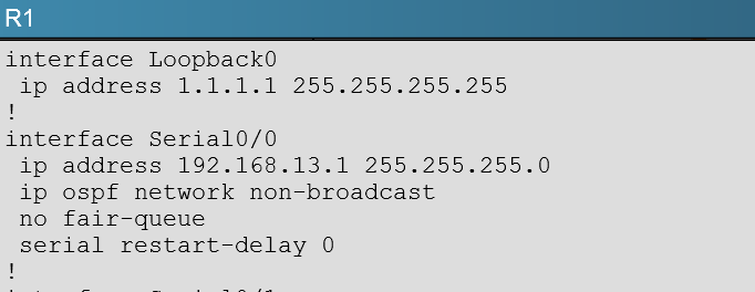
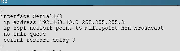
This can be seen by issuing the "show running-config" command on each router, or the "show ip ospf interface" command:
C
In order for two OSPF routers to become neighbors, they must have matching network types across the links. In this case, we see that R1 has been configured as non-broadcast and R3 is using point to point non-broadcast.
This can be seen by issuing the "show running-config" command on each router, or the "show ip ospf interface" command:
Question #12
Scenario:
A customer network engineer has edited their OSPF network configuration and now your customer is experiencing network issues. They have contacted you to resolve the issues and return the network to full functionality.


Connectivity from R3 to R4, R5 and R6 has been lost. How should connectivity be reestablished?
A customer network engineer has edited their OSPF network configuration and now your customer is experiencing network issues. They have contacted you to resolve the issues and return the network to full functionality.
Connectivity from R3 to R4, R5 and R6 has been lost. How should connectivity be reestablished?
- AConfigure R4 with a virtual link to 192.168.13.2
- BChange the R3 and R4 hello-interval and retransmit-interface timers to zero so the link won't go down.
- CAdd an OSPF network statement for 4.4.4.4 0.0.0.0 area 1 in R3
- DAdd an OSPF network statement for 192.168.34.3 0.0.0.255 area 2 in R3
- EAdd an OSPF network statement for 192.168.34.0 0.0.0.255 area 1 in R3
Correct Answer:
E
Based on the network diagram, we know that a virtual link will need to be configured to logically connect area 2 to the back area 0. However, this is not the problem as we can see that R3 has been correctly configured to do this. It is, however, missing the network statement for the link to R4.
Here, we see that the link to R4 is using the 192.168.34.0 network, but that this network has not been added to OSPF
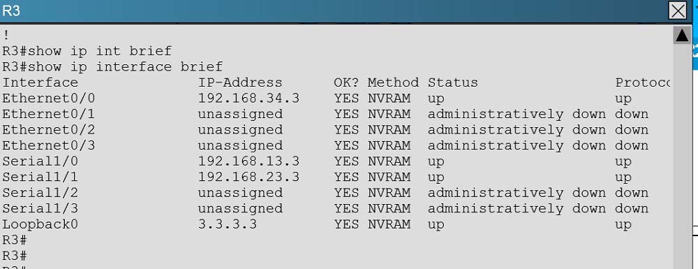
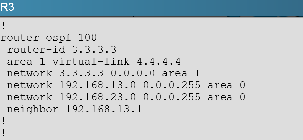
Based on the network diagram, this link should be added to Area 1, not Area 2.
E
Based on the network diagram, we know that a virtual link will need to be configured to logically connect area 2 to the back area 0. However, this is not the problem as we can see that R3 has been correctly configured to do this. It is, however, missing the network statement for the link to R4.
Here, we see that the link to R4 is using the 192.168.34.0 network, but that this network has not been added to OSPF
Based on the network diagram, this link should be added to Area 1, not Area 2.
Question #13
Scenario:
A customer network engineer has edited their OSPF network configuration and now your customer is experiencing network issues. They have contacted you to resolve the issues and return the network to full functionality.


After resolving the issues between R3 and R4. Area 2 is still experiencing routing issues. Based on the current router configurations, what needs to be resolved for routes to the networks behind R5 to be seen in the company intranet?
A customer network engineer has edited their OSPF network configuration and now your customer is experiencing network issues. They have contacted you to resolve the issues and return the network to full functionality.
After resolving the issues between R3 and R4. Area 2 is still experiencing routing issues. Based on the current router configurations, what needs to be resolved for routes to the networks behind R5 to be seen in the company intranet?
- AConfigure R4 and R5 to use MD5 authentication on the Ethernet interfaces that connect to the common subnet.
- BConfigure Area 1 in both R4 and R5 to use MD5 authentication.
- CAdd ip ospf authentication-key 7 BEST to the R4 Ethernet interface that connects to R5 and ip ospf authentication-key 7 BEST to R5 Ethernet interface that connects to R4.
- DAdd ip ospf authentication-key CISCO to R4 Ethernet 0/1 and add area 2 authentication to the R4 OSPF routing process. D
Correct Answer:
Explanation
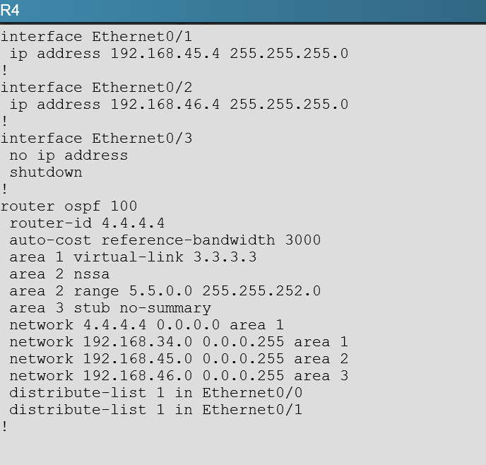
Here, we see from the running configuration of R5 that OSPF authentication has been configured on the link to R4:
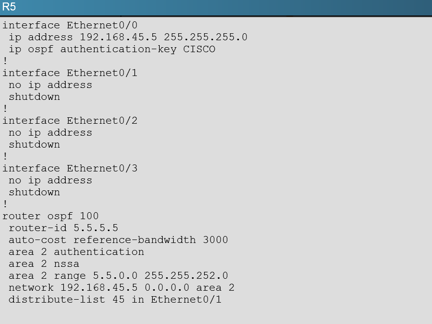
However, this has not been done on the link to R5 on R4:
Explanation
Here, we see from the running configuration of R5 that OSPF authentication has been configured on the link to R4:
However, this has not been done on the link to R5 on R4:
Question #14
Scenario:
A customer network engineer has edited their OSPF network configuration and now your customer is experiencing network issues. They have contacted you to resolve the issues and return the network to full functionality.


The 6.6.0.0 subnets are not reachable from R4. How should the problem be resolved?
A customer network engineer has edited their OSPF network configuration and now your customer is experiencing network issues. They have contacted you to resolve the issues and return the network to full functionality.
The 6.6.0.0 subnets are not reachable from R4. How should the problem be resolved?
- AEdit access-list 46 in R6 to permit all the 6.6.0.0 subnets
- BApply access-list 46 in R6 to a different interface
- CApply access-list 1 as a distribute-list out under router ospf 100 in R4
- DRemove distribute-list 64 out on R6
- ERemove distribute-list 1 in ethernet 0/1 in R4
- FRemove distribute-list 1 in ethernet 0/0 in R4 D
Correct Answer:
Explanation
Here we see from the running configuration of R6 that distribute list 64 is being used in the outbound direction to all OSPF neighbors.
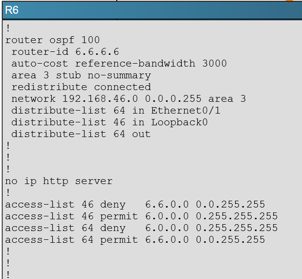
However, no packets will match the 6.6.0.0 in this access list because the first line blocks all 6.0.0.0 networks, and since the 6.6.0.0 networks will also match the first line of this ACL, these OSPF networks will not be advertised because they are first denied in the first line of the ACL.
Explanation
Here we see from the running configuration of R6 that distribute list 64 is being used in the outbound direction to all OSPF neighbors.
However, no packets will match the 6.6.0.0 in this access list because the first line blocks all 6.0.0.0 networks, and since the 6.6.0.0 networks will also match the first line of this ACL, these OSPF networks will not be advertised because they are first denied in the first line of the ACL.
Question #15
Instructions -
The main screen consists of two parts; the Main scenario and the Topology tabs. The main scenario describes TSHOOT.com test bed. The Topology tabs allow you to display the appropriate and select the trouble ticket.
To complete the item, you will first need to familiarize yourself with the TSHOOT.com test bed by clicking on the master scenario first and then the topologies tabs.
Once you are familiar with the test bed and the topologies, you should start evaluating the trouble ticket. You will be presented with a Trouble Ticket scenario that will describe the fault condition. You will need to determine on which device the fault condition is located, to which technology the fault condition is related, and the solution to each trouble ticket. This will be done by answering three questions.
Ticket Selection -
✑ To begin, click on the Ticket on the Topology tabs.
Some of the questions will require you to use the scroll bar to see all options.
✑ Please note.
Fault Isolation -
✑ Read the ticket scenario to understand the fault condition.
✑ Open the appropriate topology, based upon the ticket scenario.
✑ Open the console of the desired device by clicking on that device in the topology, based upon your troubleshooting methodology.
✑ Use the supported show, ping and trace commands to begin your fault isolation process.
✑ Move to other devices as need by clicking on those devices within the topology.
Fault Identification -
✑ The trouble ticket will include three questions that you will need to answer:
1. Which device contains the fault
2. Which technology the fault condition is related to
3. What is the solution to the issue
✑ To advance to the next question within the ticket click on "Next Question".
✑ When you click "DONE", the trouble ticket will turn RED and will no longer be accessible.
✑ You may also use the "Previous Question" button to review questions within that specific ticket.
✑ To complete a trouble ticket, answer all three questions and click "DONE". This will store your response to the questions. Do not click on "DONE" unless you have answered all questions within the ticket.
Item Completion -
✑ Click the NEXT button on the bottom of the screen once a ticket is RED. This action moves you to the next item.
Scenario -
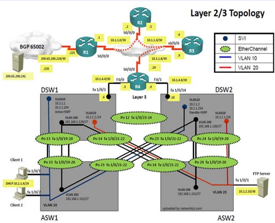
The company has created the test bed network shown in the layer 2 and layer 3 topology exhibits.
This network consists of four routers, two layer 3 switches and two layer 2 switches.
In the IPv4 layer 3 topology, R1, R2, R3, and R4 are running OSPF with an OSPF process number 1.
DSW1, DSW2 and R4 are running EIGRP with an AS of 10. Redistribution is enabled where necessary.
R1 is running a BGP AS with a number of 65001. This AS has an eBGP connection to AS 65002 in the ISP's network. Because the company's address space is in the private range, R1 is also providing NAT translations between the inside (10.1.0.0/16 & 10.2.0.0/16) networks and the outside (209.65.200.0/24) network.
ASW1 and ASW2 are layer 2 switches.
NTP is enabled on all devices with 209.65.200.226 serving as the master clock source.
The client workstations receive their IP address and default gateway via R4's DHCP server. The default gateway address of 10.2.1.254 is the IP address of HSRP group 10 which is running on DSW1 and DSW2.
In the IPv6 layer 3 topology R1, R2, and R3 are running OSPFv3 with an OSPF process number 6. DSW1, DSW2 and R4 are running RIPng process name
RIP_ZONE. The two IPv6 routing domains, OSPF 6 and RIPng are connected via GRE tunnel running over the underlying IPv4 OSPF domain. Redistribution is enabled where necessary.
Recently the implementation group has been using the test bed to do a "˜proof-of-concept' on several implementations. This involved changing the configuration on one or more of the devices. You will be presented with a series of trouble tickets related to issues introduced during these configurations.
The implementation group has been using the test bed to do a "˜proof-of-concept' that requires both Client 1 and Client 2 to access the WEB Server at
209.65.200.241. After several changes to the network addressing, routing schemes, DHCP services, NTP services, and FHRP services, a trouble ticket has been opened indicating that Client 1 cannot ping the 209.65.200.241 address.
Use the supported commands to isolate the cause of this fault and answer the following questions.
On which device is the fault condition located?
The main screen consists of two parts; the Main scenario and the Topology tabs. The main scenario describes TSHOOT.com test bed. The Topology tabs allow you to display the appropriate and select the trouble ticket.
To complete the item, you will first need to familiarize yourself with the TSHOOT.com test bed by clicking on the master scenario first and then the topologies tabs.
Once you are familiar with the test bed and the topologies, you should start evaluating the trouble ticket. You will be presented with a Trouble Ticket scenario that will describe the fault condition. You will need to determine on which device the fault condition is located, to which technology the fault condition is related, and the solution to each trouble ticket. This will be done by answering three questions.
Ticket Selection -
✑ To begin, click on the Ticket on the Topology tabs.
Some of the questions will require you to use the scroll bar to see all options.
✑ Please note.
Fault Isolation -
✑ Read the ticket scenario to understand the fault condition.
✑ Open the appropriate topology, based upon the ticket scenario.
✑ Open the console of the desired device by clicking on that device in the topology, based upon your troubleshooting methodology.
✑ Use the supported show, ping and trace commands to begin your fault isolation process.
✑ Move to other devices as need by clicking on those devices within the topology.
Fault Identification -
✑ The trouble ticket will include three questions that you will need to answer:
1. Which device contains the fault
2. Which technology the fault condition is related to
3. What is the solution to the issue
✑ To advance to the next question within the ticket click on "Next Question".
✑ When you click "DONE", the trouble ticket will turn RED and will no longer be accessible.
✑ You may also use the "Previous Question" button to review questions within that specific ticket.
✑ To complete a trouble ticket, answer all three questions and click "DONE". This will store your response to the questions. Do not click on "DONE" unless you have answered all questions within the ticket.
Item Completion -
✑ Click the NEXT button on the bottom of the screen once a ticket is RED. This action moves you to the next item.
Scenario -
The company has created the test bed network shown in the layer 2 and layer 3 topology exhibits.
This network consists of four routers, two layer 3 switches and two layer 2 switches.
In the IPv4 layer 3 topology, R1, R2, R3, and R4 are running OSPF with an OSPF process number 1.
DSW1, DSW2 and R4 are running EIGRP with an AS of 10. Redistribution is enabled where necessary.
R1 is running a BGP AS with a number of 65001. This AS has an eBGP connection to AS 65002 in the ISP's network. Because the company's address space is in the private range, R1 is also providing NAT translations between the inside (10.1.0.0/16 & 10.2.0.0/16) networks and the outside (209.65.200.0/24) network.
ASW1 and ASW2 are layer 2 switches.
NTP is enabled on all devices with 209.65.200.226 serving as the master clock source.
The client workstations receive their IP address and default gateway via R4's DHCP server. The default gateway address of 10.2.1.254 is the IP address of HSRP group 10 which is running on DSW1 and DSW2.
In the IPv6 layer 3 topology R1, R2, and R3 are running OSPFv3 with an OSPF process number 6. DSW1, DSW2 and R4 are running RIPng process name
RIP_ZONE. The two IPv6 routing domains, OSPF 6 and RIPng are connected via GRE tunnel running over the underlying IPv4 OSPF domain. Redistribution is enabled where necessary.
Recently the implementation group has been using the test bed to do a "˜proof-of-concept' on several implementations. This involved changing the configuration on one or more of the devices. You will be presented with a series of trouble tickets related to issues introduced during these configurations.
The implementation group has been using the test bed to do a "˜proof-of-concept' that requires both Client 1 and Client 2 to access the WEB Server at
209.65.200.241. After several changes to the network addressing, routing schemes, DHCP services, NTP services, and FHRP services, a trouble ticket has been opened indicating that Client 1 cannot ping the 209.65.200.241 address.
Use the supported commands to isolate the cause of this fault and answer the following questions.
On which device is the fault condition located?
All Pages