Cisco® 300-115 Exam Practice Questions (P. 3)
- Full Access (992 questions)
- One Year of Premium Access
- Access to one million comments
- Seamless ChatGPT Integration
- Ability to download PDF files
- Anki Flashcard files for revision
- No Captcha & No AdSense
- Advanced Exam Configuration
Question #23
Refer to the exhibit.
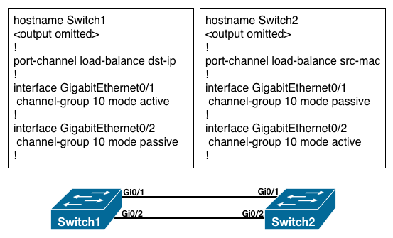
What is the result of the configuration?
What is the result of the configuration?
- AThe EtherChannels would not form because the load-balancing method must match on the devices.
- BThe EtherChannels would form and function properly even though the load-balancing and EtherChannel modes do not match.
- CThe EtherChannels would form, but network loops would occur because the load-balancing methods do not match.
- DThe EtherChannels would form and both devices would use the dst-ip load-balancing method because Switch1 is configured with EtherChannel mode active.
Correct Answer:
B
An etherchannel will form if one end is active and the other is passive. The table below summarizes the results for LACP channel establishment based on the configuration of each side of a link:
LACP Channel Establishment -
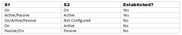
Load balancing can only be configured globally. As a result, all channels (manually configured, PagP, or LACP) use the same load-balancing. This is true for the switch globally, although each switch involved in the etherchannel can have non matching parameters for load balancing.
Reference: http://www.cisco.com/c/en/us/td/docs/switches/lan/catalyst4500/12-2/54sg/configuration/guide/config/channel.html#wp1020804
B
An etherchannel will form if one end is active and the other is passive. The table below summarizes the results for LACP channel establishment based on the configuration of each side of a link:
LACP Channel Establishment -
Load balancing can only be configured globally. As a result, all channels (manually configured, PagP, or LACP) use the same load-balancing. This is true for the switch globally, although each switch involved in the etherchannel can have non matching parameters for load balancing.
Reference: http://www.cisco.com/c/en/us/td/docs/switches/lan/catalyst4500/12-2/54sg/configuration/guide/config/channel.html#wp1020804
All Pages